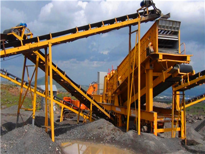
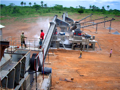
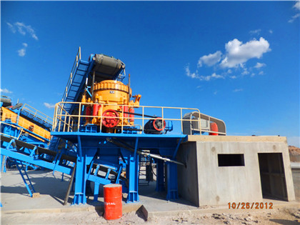
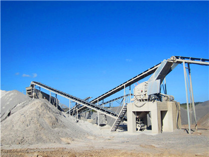
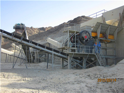
Assembly drawing of belt conveyor Download Scientific Diagram
Assembly drawing of belt conveyor Download Scientific Diagram Figure 1 uploaded by S J Ojolo Content may be subject to copyright Download View publication Assembly Browse and download thousands of CAD Drawing files Thousands of free, manufacturer specific CAD Drawings, Blocks and Details for download in multiple 2D and 3D formats Download Free, High Quality CAD Drawings CADdetails
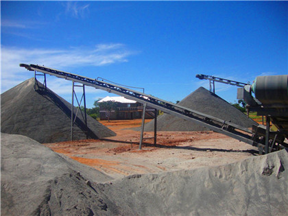
Schematic diagram of the doublehead driving belt conveyor 1:
Schematic diagram of the doublehead driving belt conveyor 1: Driving roller 1 2: Driving roller 2 3: Tension device 4: Supporting roller 5: Conveyor belt 7: Driving device 2 8:A schematic diagram of the main conveyor belt with an accumulating bunker at the input is shown in Fig 1 [12] The flow of the material (for example, a rock) should enter the Schematic diagram of the conveyor belt [12] ResearchGate
FIELD SERVICE MANUAL Rexnord
The layout shown below illustrates a basic belt conveyor Unlimited variations of elevation, loading, discharge, idlers, their spacing, pulleys and accessories are possible THE The conveyor belt represents one of the most commonly used methods of transporting bulk materials today As highlighted multiple times in research, the moving parts are a critical Scheme of a conveyor belt Download Scientific Diagram
Dynamic Analysis of Mechanical Conveyor Drive System
The article deals with the dynamic analysis of the mechanical system of the drive to the conveyor belt Subject of the investigation is the behavior of the mechanical Browse 206 conveyor belt drawing photos and images available, or start a new search to explore more photos and images Browse Getty Images' premium collection of highquality, authentic Conveyor Belt Drawing stock photos, royaltyfree images, and pictures Conveyor Belt Drawing stock photos are available in a variety of sizes and formats to fit206 Conveyor Belt Drawing Stock Photos & HighRes Pictures
Belt Conveyors for Bulk Materials Fifth Edition Chapter 6
89 Belt Tension Calculations W b =weight of belt in pounds per foot of belt length When the exact weight of the belt is not known, use average estimated belt weight (see Table 61) W m =weight of material, lbs per foot of belt length: Three multiplying factors, K t,K x,and K y,are used in calculations of three of the components of the effective belt tension, TFigure 2 represents a longitudinal view of the material traveling at v = 33 ¯ 3 m/s on an 8km conveyor belt, where the height of material above the bottom belt surface represents the magnitudeSimplified sketch of a conveyor Download
Conveyor Belt Drawing High Res Illustrations Getty Images
conveyor line icon, sketch design, pixel perfect, editable stroke logo, sign, symbol cargo, product line, package, factory, delivery conveyor belt drawing stock illustrations a young woman carries out quality control vector illustration of factory production line and conveyor belt design concept hand drawn, sketch, doodle conveyor belt drawing stock A drawing of the conveyor is shown below in Figure 1 Figure 1 Conveyor Simulator Engineering Requirements for project Special features: x La bVIEW so ftware development environment x Pre built conveyor simulator used for the control system x Conveyor simulator interfaced to the NI USB 6008 DAQ card 6 age 223833Conveyor Control System Project American Society for
Belt Conveyor an overview ScienceDirect Topics
10231 Belt conveyors Belt conveyors are the most widely used and versatile mode of mechanical conveying systems employed to transport materials horizontally or on an inclined either up or down Fig 101, represents a typical beltconveyor arrangement, with the following main components of the system: Figure 101Above belt conveyor designed according to Indian standards (IS11592) It consists of tension calculations on pulley, stress analysis on pulley, on components of belt conveyor and its effect 3D CADDesign of Belt Conveyor System ResearchGate
FIELD SERVICE MANUAL Rexnord
Installation of Belt On conveyors with short centers (200300 feet), there should be no problem in removing all of the slack from the belt On conveyors with long centers, it may be necessary to take two hitches while stringing the belt; one to remove slack on the return side, Œ then a second hitch on the carrying side It is important toTranscribed Image Text: Q: Figure (1) shows a schematic drawing of a countershaft which is part of the conveyor system and supports two belt pulleys (A & B) The belt tensions are parallel for pulley B and inclined with angle 45° for pulley A The pulley A receives a power from a motor and then delivers to conveyor belt through pulley BAnswered: Q: Figure (1) shows a schematic drawing bartleby
Volume 3, Issue 1, July 2013 Modelling a Nonlinear Conveyor Belt
by a general schematic diagram in Fig 1 This subsection provides a concise conveyor belt system description Fig 1: Schematic Block Diagram of a Conveyor System A Controller and Feedback Channel The aim of the controller and the feedback channel is to continuously monitor any deviations on the system output byconveyor belt is normally referred to as the "carcass" In a sense, the carcass is the heart of the conveyor belt since it must: 1 Provide the tensile strength necessary to move the loaded belt 2 Absorb the impact of the impinging material being loaded onto the conveyor belt 3 Provide the bulk and lateral stiffnessConveyor Belt Manual IBT Industrial Solutions
Design of Conveyor Control Information System Considering Transport
This simplicity is due to the following feature: all elements that are on the conveyor belt within the conveyor section move at the same speed equal to the speed of the conveyor belt The carrying capacity control of the conveyorbased transport system comes down to controlling the intensity of the material entering the conveyor section One common cause of conveyor belt slippage is exceeding the conveyor system’s weight limit when transporting materials and products When a conveyor belt tries to move things heavier than Common Causes of Conveyor Belt Slippage
The multilayer belt conveyor dryer configuration and
Download scientific diagram The multilayer belt conveyor dryer configuration and characteristics of the serrated border (a) schematic drawing of the belt dryer with measurement points (rightThe conveyor is driven by the motor Conveyors are used to transport items from one location to another Infrared (IR) sensors are used to measure the dimensions at the top of the conveyor ThisSchematic of conveyor pulley drive unit (viewed from top)
Typical failure analysis and processing of belt conveyor
Fig1 Installs the schematic drawing Fig 2 Adjusts the heart principle Manufacture installation quality of roller directly affect the life and running resistance of conveyor belt roller repair and replacement costs are also an important part Schematic diagram of mechanical conveyor belt drive system 261 Stanislav GrambliÄ ka et al / Procedia Engineering 192 ( 2017 ) 259 – 264 Explanatory notes to figure 1: x Ȧ1 the angular speed of the electric motor (rads1) x Ȧ2 the angular speed of the gear box (rads1) x Ȧ3 the angular speed of the conveyor (rads1) xDynamic Analysis of Mechanical Conveyor Drive System
Structure of belt conveyer / conveyor KENKI Corporation
Structure of belt conveyor 1 Frame Frame is a structure which shapes a belt conveyor There are mainly two types 1)Stringer frame Frame made by shaped steel, bended steel plate, etc Main body of conveyor can be made with low cost This frame is used mostly in conveyor frame using resin conveyor belt which is for light If the belt is Vguided (Vguided belts are ideal for reversing and side exiting applications where belt tracking might otherwise be difficult to maintain), verify the guide is straight along the entire belt 12 CONVEYOR PREPARATION Before beginning the installation process, have a firm understanding of the belt routing for the conveyor UseBelt Installation, Tracking, and Maintenance Guide LEWCO, Inc
Safe and reliable conveyor belt control, always ready for action
The alignment switches are mounted on both sides of conveyor systems to provide a failsafe mechanism for conveyor belts that have misaligned to the left or right Alignment switches are typically mounted on either side of the header and tail pulleys on all conveyors, after every 300 meters and at every tripper drive on longer conveyor belts